The Teeces 32 is the next-generation controller for R2-D2 style dome logic displays (FLD, RLD) and Process State Indicators (PSI). It replaces the classic Arduino-based controllers (like the Teeces V4 and CuriousMarc v1.4) with a modern, powerful ESP32-C3 Mini development board.
While it maintains compatibility with the JawaLite command protocol and the MAX7219-based logic display hardware, this new system introduces significant performance upgrades and powerful new features.
Available at shop.printed-droid.com

1. Core Hardware & Architecture
Controller
The primary change is the move from an Arduino Pro Mini/Nano to an ESP32-C3 Mini. This powerful microcontroller provides more processing power, more memory, and built-in features, allowing for a much more advanced feature set.
Logic Displays (FLD & RLD)
The Front Logic Displays (FLD) and Rear Logic Display (RLD) are still controlled using the traditional method: MAX7219 LED matrix drivers connected in a daisy chain. The ESP32 firmware manages two separate SPI chains:
- Rear Chain: Controls the RLD (and analog Rear PSI).
- Front Chain: Controls the Top FLD, Bottom FLD, and analog Front PSI.
2. Key Feature: Dual PSI Support (Analog & Digital)
This is the most significant functional upgrade. The Teeces 32 firmware can operate in one of two global modes for the Process State Indicators (PSIs). This mode is set in the configuration menu and applies to all profiles.

A) Analog PSI Mode (Classic)
This is the “classic” mode, compatible with older Teeces V3/V4 PSI boards.
- Hardware: Uses the MAX7219 drivers on the Front and Rear chains to control standard LEDs.
- Function: Animates between two pre-defined colors (typically “Color 1” and “Color 2”, which correspond to the physical red/blue or yellow/green LEDs installed on the board).
B) Digital PSI Mode (New)
This mode utilizes the ESP32’s ability to control modern addressable LEDs directly.
- Hardware: Drives digital (NeoPixel/WS2812B) LED strips connected to dedicated GPIO pins (GPIO8 and GPIO9).
- Function: This enables full RGB color control. You are no longer limited to two physical colors. The firmware provides a palette of 12 pre-defined colors (e.g., RED, GREEN, BLUE, YELLOW, CYAN, MAGENTA, WHITE, PINK) that you can assign to “Color 1” and “Color 2” for the PSI animations.
3. Advanced Software Features (v4.1)
The ESP32 controller enables a suite of modern software features not possible on the Arduino platform.
Interactive Serial Menu
Configuration is no longer done by editing #define constants in the code. You can now access a powerful live configuration menu.
- Access: Connect via a serial monitor at 9600 baud and send a single
*character. (Note: This is faster than the 2400 baud default of older versions). - Function: Allows you to change all system settings on the fly without recompiling or reflashing the firmware.
Persistent Configuration
All settings changed via the serial menu are saved to the ESP32’s flash memory (using the Preferences library). This means your brightness, colors, speeds, and profile selections are retained even after a power loss.
Profile Management System
The system supports 5 distinct setting profiles:
- Profile 1 (Standard): A fixed, non-editable default profile.
- Profile 2 (Custom/KT): A fixed profile showcasing digital PSIs in White & Pink.
- Profiles 3, 4, 5 (User): Three fully customizable slots where you can save your own configurations.
System Stability
A Watchdog Timer (WDT) is implemented. If the main software loop ever freezes, the WDT will automatically reboot the controller, ensuring maximum reliability.
4. New User Experience Tools (v4.1)
Version 4.1 introduces several tools to simplify setup and use:
- Setup Wizard: A
wizardcommand provides a guided, step-by-step setup for first-time users. - Hardware Diagnostics: A
diagnosticscommand will test all connected components (Flash, FLDs, RLD, and both analog/digital PSIs) to help troubleshoot wiring. - Quick Presets: Includes 5 built-in presets (
Bright,Dim,KT,Classic,Rainbow) that can be loaded instantly. - Smart Suggestions: The config menu provides context-aware tips to help you understand settings.
- Enhanced Validation: Provides clear hints and valid ranges when you enter an incorrect parameter value.
5. Protocol & Command Compatibility
The Teeces 32 system remains fully compatible with the JawaLite Serial Protocol, just like its predecessors. It accepts the same standard commands for integration with other controllers:
- T Commands (Display States):
0T1(Random),0T0(Test),0T20(Off),0T6(Leia),0T100(Text Mode), etc.. - M Commands (Text):
1MHELLO WORLD(Set display text). - P Commands (Alphabet):
0P60(Latin),0P61(Aurabesh). - R Commands (Random Style):
0R4(Set random pattern density). - S Commands (PSI State):
4S1(Front PSI Random),4S2(Front PSI Color 1),4S4(Front PSI Off).
6. Wiring (ESP32-C3 Mini)
Boards and Wiring:
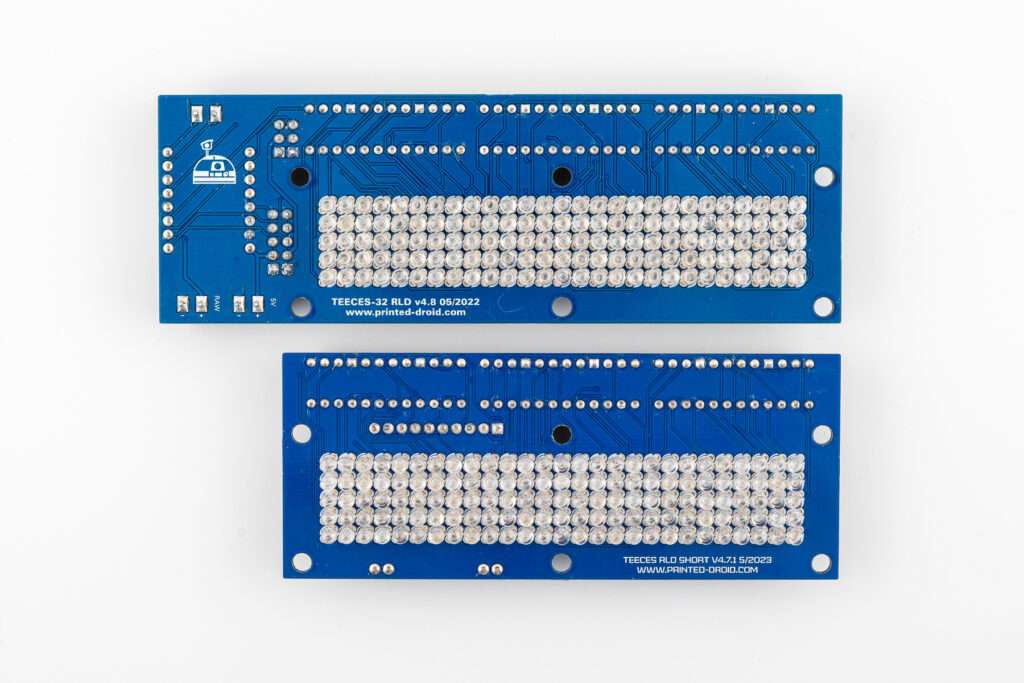
1. RLD-Board (Rear Logic Board)
- This board forms the foundation of the system.
- On the back of the RLD-Board is the Control Board, which manages the system’s operation. (Only Slim Teeces)
2. Control Board
The Control Board is directly connected to the RLD-Board and features six connections:
- RAW-Input: Input for up to 12V (not recommended but possible).
- 5V-Input: Recommended input as it provides stable power supply for the system.
- RX/TX (Serial Communication): Terminal for serial data transmission (receive and send).
- Three 5 PIN connections:
- OUT-2-Front: For the front components.
- OUT-1-Rear: For the rear components (where the PSI-Board is connected).
- Input: Not currently used.
3. Wiring of the 2 Front Logic Boards (FLD) and the Front PSI Board
- The OUT-2-Front connection of the Control Board is connected to the Input of the first Front Logic Board (FLD).
- From the OUT of the first FLD, the connection continues to the Input of the second FLD.
- From the OUT of the second FLD, the connection goes to the Input of the Front PSI Board.
- All connections use a 5-pin cable, wired pin-to-pin:
- The pins Plus, Minus, L, C, and D must be connected 1-to-1 to ensure correct communication between the components.
4. Wiring of the Rear PSI Board
- The OUT-1-Rear connection of the Control Board is connected to the Rear PSI Board (Process Status Indicator).
- The connection is made using a 5-pin cable, wired pin-to-pin:
- The pins Plus, Minus, L, C, and D must be connected 1-to-1 to ensure correct data transmission.
- This connection runs directly from the Control Board to the input of the Rear PSI Board.
5. Wiring of the digital PSI Boards
- The digital PSIs are connected to the pin headers labeled
PSI1andPSI2.
Softwareguide:
1. Introduction
This manual provides a complete guide for the Printed Droid Teeces Logic Display Controller – ESP32 Enhanced Version 4.1. This advanced controller is designed to run on an ESP32, providing a stable, feature-rich, and highly configurable solution for your R2-D2’s logic displays.
The system controls Front Logic Displays (FLD), Rear Logic Display (RLD), and Process State Indicators (PSI). It has been enhanced from its base version to include persistent settings (saved to flash memory), a comprehensive interactive serial menu for configuration, a watchdog timer for stability, and a powerful profile management system.
Version 4.1 introduces user-friendly features like a Setup Wizard, a Hardware Diagnostics tool, and Quick Presets to make configuration easier than ever.
2. Hardware Requirements & Wiring
2.1. Required Components
- Controller: ESP32-C3 Mini development board.
- Display Drivers: MAX7219 LED matrix controllers (daisy-chained).
- LED Matrices: 5×9 matrices for Front Logic Displays (FLD) and a 5×27 matrix for the Rear Logic Display (RLD).
- PSIs (Choose one):
- Analog PSIs: LED arrays driven by the MAX7219 chain.
- Digital PSIs: Two 26-LED digital strips (e.g., NeoPixel/WS2812B). The default PSI mode for this firmware is DIGITAL.
2.2. Default Wiring (ESP32-C3 Mini)
The firmware is pre-configured for the following pinout:
- Rear Chain (RLD + Rear Analog PSI):
- DATA: GPIO7, CLK: GPIO6, CS: GPIO5
- Front Chain (TFLD + BFLD + Front Analog PSI):
- DATA: GPIO4, CLK: GPIO3, CS: GPIO2
- Digital PSI 1:
- DATA: GPIO8
- Digital PSI 2:
- DATA: GPIO9
3. Getting Started (First-Time Use)
3.1. Connect to the Controller
- Connect to your ESP32-C3 Mini via USB.
- Open a serial monitor (like the one in the Arduino IDE).
- Set the baud rate to 9600.
- You should see the welcome message for Teeces v4.1. If it’s your first time, you’ll see a special message.
3.2. Run the Setup Wizard
For the easiest first-time setup, the controller includes a guided wizard.
- In the serial monitor, type
*and press Enter to enter the configuration menu. - At the
Config>prompt, typewizardand press Enter. - The wizard will guide you through the following steps:
- Step 1: PSI Type: Choose between Analog (MAX7219) or Digital (NeoPixel) PSIs.
- Step 2: Brightness: Select a brightness level for dark, normal, or bright environments.
- Step 3: PSI Colors: If you selected Digital PSI, choose a color scheme (e.g., Classic, Movie Accurate, Modern).
- Step 4: Save Profile: Save your settings to one of the user profiles (3, 4, or 5).
- After completion, your droid is configured and ready. The wizard will also mark the first-time setup as complete.
4. Normal Operation (JawaLite Serial Commands)
The controller responds to standard “JawaLite” protocol commands at 9600 baud. This allows it to be controlled by other droid components (like a Marcduino) or via the serial monitor.
Format: [address][command][argument]<CR> (where <CR> is a carriage return).
4.1. Addresses
| Address | Target |
0 | All displays |
1 | Top FLD |
2 | Bottom FLD |
3 | Rear LD |
4 | Front PSI |
5 | Rear PSI |
4.2. T Commands (Display State)
| Command | Function |
T0 | Test mode (all LEDs on) |
T1 | Random mode |
T2 / T3 / T5 | Alarm effect |
T4 | Failure effect |
T6 | Leia effect |
T10 | Star Wars text |
T11 | March effect |
T20 | Off (display blank) |
T92 | Bargraph mode |
T100 | Text mode (displays text set by M command) |
4.3. M Commands (Text)
M[text]: Sets the text to be displayed.- Example:
1MHELLO WORLDsets the Top FLD to scroll “HELLO WORLD”.
4.4. P Commands (Alphabet)
| Command | Function |
P60 | Use Latin alphabet |
P61 | Use Aurabesh alphabet |
4.5. R Commands (Random Style)
R[0-6]: Sets the density of the random display mode.0= Sparse,6= Dense.
4.6. S Commands (PSI State)
| Command | Function |
S0 | Test (all on) |
S1 | Random mode |
S2 | Color 1 |
S3 | Color 2 |
S4 | Off |
5. Interactive Configuration Menu
This is the most powerful feature of the controller. It allows you to customize and save every aspect of your displays.
To access: Send a single * character in the serial monitor.
You will see a Config> prompt. From here, you can enter commands to view, change, and save settings. The status line shows your active profile, PSI mode, and if you have unsaved changes.
5.1. Main Commands
| Command | Function |
help | Shows a detailed list of commands and examples. |
show | Displays all settings for the currently active profile. |
wizard | Runs the first-time setup assistant. |
diagnostics | Runs a hardware test on all displays and PSIs. |
presets | Shows a list of 5 Quick Presets. |
preset <1-5> | Applies a Quick Preset (e.g., preset 3). |
colors | Lists the 12 available colors for digital PSIs and their index numbers. |
set <param> <val> | Changes a setting (see section 5.4). |
profile ... | Manages profiles (see section 5.2). |
exit | Exits the config menu and resumes normal operation. |
5.2. Profile Management
The controller supports 5 profiles for all settings.
- Profile 1 (Standard): A fixed, non-editable default profile.
- Profile 2 (Custom): A fixed profile set up for digital PSIs in White & Pink.
- Profiles 3, 4, 5 (User): Fully customizable and saved persistently.
| Command | Function |
profile show | Displays the currently active profile number (1-5). |
profile load <1-5> | Loads and activates the specified profile. |
profile save | Saves changes to the current user profile (3, 4, or 5 only). |
profile reset <3-5> | Resets a user profile (3, 4, or 5) back to default settings. |
5.3. Quick Presets
Presets are pre-configured settings for common use cases. Applying a preset modifies your current profile. You must use profile save to keep the changes (on profiles 3-5).
| Preset | Name | Description |
| 1 | Bright | Maximum brightness, fast scrolling |
| 2 | Dim | Low brightness for dark environments |
| 3 | KT | Colorful KT mode (White/Pink PSI) |
| 4 | Classic | Original analog PSI look |
| 5 | Rainbow | Colorful digital PSI rotation |
Usage:
- Type
presetsto see the list. - Type
preset 3to apply the “KT” preset. - Type
profile saveto save these new settings to your user profile.
5.4. Hardware Diagnostics
If you are troubleshooting, the diagnostics command will test all components.
- Flash Memory
- Rear Logic Display
- Front Logic Displays
- Analog PSIs (Rear and Front)
- Digital PSI 1 (GPIO8) and 2 (GPIO9)
- Watchdog Timer
The tool also provides troubleshooting tips for common wiring issues.
5.5. All Configuration Parameters
Use the set <parameter> <value> command to change settings (e.g., set scroll_speed 50). Use show to see the current values.
Global Setting (Applies to ALL profiles)
psi_output: Sets the PSI type.0= Analog (MAX7219),1= Digital (NeoPixel).
Brightness Settings (Per-Profile)
rld_bright <0-15>: Rear Logic Display brightness.fld_bright <0-15>: Front Logic Displays brightness.rpsi_bright <0-15>: Rear PSI brightness.fpsi_bright <0-15>: Front PSI brightness.
Behavior & Timing (Per-Profile)
logic_style <0-6>: Random display density (0=sparse, 6=dense).logic_delay <ms>: Random display update speed (e.g., 150).scroll_speed <ms>: Text scroll speed (e.g., 55). Lower is faster.psi_wipe_delay <ms>: PSI animation speed (e.g., 75). Lower is faster.
Digital PSI Configuration (Per-Profile)
colors: Type this command to see the full color list (Appendix A).psi_swap <0-1>:0= Normal wiring (PSI1=Front, PSI2=Rear).1= Swapped wiring (PSI1=Rear, PSI2=Front).psi1_color1 <0-11>: Color for Front PSI, pattern 1.psi1_color2 <0-11>: Color for Front PSI, pattern 2.psi2_color1 <0-11>: Color for Rear PSI, pattern 1.psi2_color2 <0-11>: Color for Rear PSI, pattern 2.
PSI “Stuck” Effect (Per-Profile)
fpsi_stuck <0-1>:1= Enable “stuck” effect on Front PSI,0= Disable.rpsi_stuck <0-1>:1= Enable “stuck” effect on Rear PSI,0= Disable.psi_stuck_time <ms>: How long the PSI stays “stuck” (e.g., 7000).psi_stuck_freq <1-100>: How often the effect happens (e.g., 10).
Boot Text (Per-Profile)
This text scrolls one time on startup.
boot_tfld <text>: Set text for Top FLD (max 31 chars).boot_bfld <text>: Set text for Bottom FLD (max 31 chars).boot_rld <text>: Set text for Rear LD (max 31 chars).- Example:
set boot_tfld HELLO R2.
6. Appendix A: Digital PSI Color Palette
Use the colors command to see this list. Use the index number (0-11) for set commands.
| Index | Color Name |
| 0 | RED |
| 1 | GREEN |
| 2 | BLUE |
| 3 | YELLOW |
| 4 | CYAN |
| 5 | MAGENTA |
| 6 | ORANGE |
| 7 | PURPLE |
| 8 | PINK |
| 9 | LIME |
| 10 | SKYBLUE |
| 11 | WHITE |
7. Appendix B: Quick Preset Definitions
| ID | Name | Description | Brightness | PSI Mode | Colors (1/2) | Logic Style | Scroll Speed |
| 1 | Bright | Max brightness, fast scroll | 15 | DIGITAL | WHITE (11) / BLUE (2) | 4 | 40ms |
| 2 | Dim | Low brightness, dark env. | 3 | DIGITAL | BLUE (2) / RED (0) | 4 | 55ms |
| 3 | KT | Colorful KT mode | 8 | DIGITAL | WHITE (11) / PINK (8) | 4 | 45ms |
| 4 | Classic | Original analog look | 5 | ANALOG | N/A | 4 | 55ms |
| 5 | Rainbow | Colorful digital rotation | 10 | DIGITAL | CYAN (4) / ORANGE (6) | 5 | 50ms |