The Data Port Logics VU is an enhanced version of the original DPL for Astromechs and has been released 2021.
The main difference to the classic DPL are the additional digital RGB Leds.
The other Leds are driven by a Maxim7219 LED driver chip as usual.
It’s a DPL with more blink blink.
With coding you can show battery status via the digital Leds, use it as a VU meter or whatever your creativity tells you.
Differences to the “regular” CBI & DPLs:
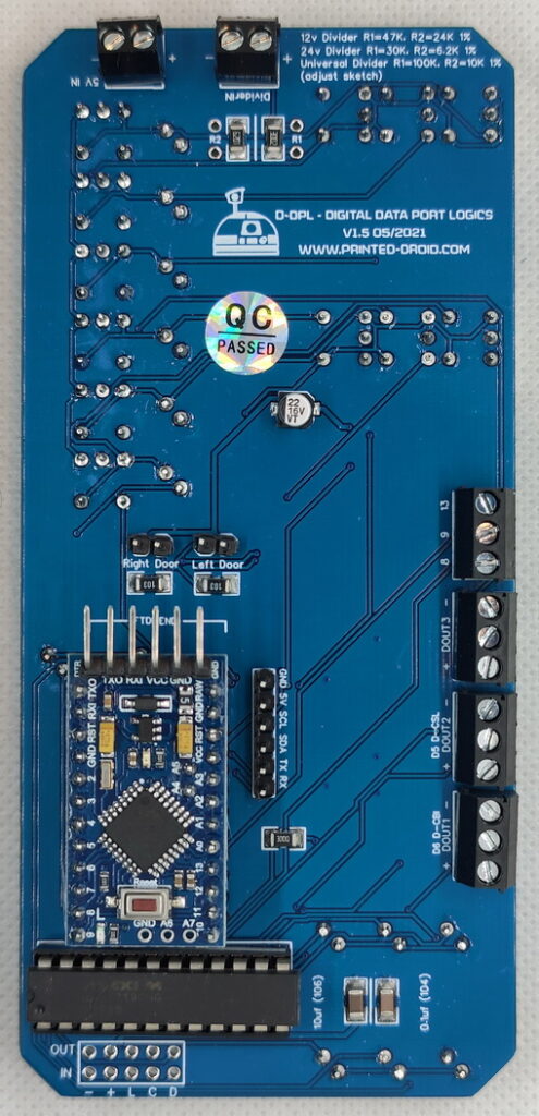
- Everything on 1 pcb – Arduino, terminals for power and voltage sensor are integrated in the DPL – even added I2C & serial breakout
- Digital VU Leds
- Terminals for the other Printed Droid Body Lights
- Better tracing
- Improved LED alignment
If you have the LDPL the sketch attached uses OUT3 for it.
Parts List for the DIY Board (Smd components are always presoldered):
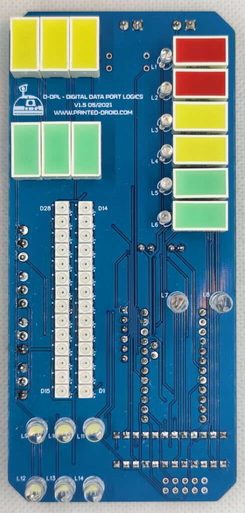
- 6x 3mm Led Blue (L1-L6)
- 2x 5mm Led Red (L7 & L8)
- 6x 6mm Led White (L9-L14)
- 2x Red Square Led (available at Mouser: DE2SURKD)
- 5x Green Square Led (available at Mouser: DE2CGKD)
- 5x Yellow Square Led (available at Mouser: DE2SYKD)
- All terminals are 3.5mm pitch and the headers (male/female) are standard 2.54mm pitch
- The driver for the analog Leds is a standard MAX7219CNG (available at Mouser)
Available at shop.printed-droid.com
Turning Panels on/off via magnet:
To make DPL and CBI turn on and off depending on whether the panel is open, Printingbuddy uploaded STLs to Makerworld to trigger a reed switch using a magnet.
The magnet is mounted on the servo horn, and when it approaches the switch, the light of the respective board turns off.
Files:
https://makerworld.com/de/models/1080664-r2-d2-dpl-door-servomount-with-reed-contact#profileId-1072371
https://makerworld.com/de/models/1080648-r2-d2-cbi-door-servomount-with-reed-contact#profileId-1072356
Pictures:


Wiring/Pinout:

UPDATE 2025:
You can use the newer firmware originally developed for the Astrocan DPL system. It’s optimized for the Arduino Nano and also works with the Pro Mini.
Firmware:
Instructions:
- Use the attached firmware file: “DPL Firmware_Nano-vXXX.hex”.
- Open the attached tool XLoader.
- In XLoader:
- Select the firmware file.
- Choose the correct COM port.
- Set the Device to Nano (ATmega328).
- Set the baud rate to 115200 or 57600 (depending on your Nano board).
- Click Upload.

Configuration Commands:
Updates on commands etc. are at Nextgenastromech.com: https://nextgenastromech.net/?page_id=540#lights
Use serial terminal to connect via USB (see above) to AstroCAN-Module. If your browser supports “Web Serial”, you also can use the terminal available in the Firmware section. Communication speed ist 115200 baud. The following commands are available for configuration and management.
Note: The light configuration parameters differ from the common AstroCAN syntax. This is due to compatibility to the Arduino Nano board with less memory.
Light Configuration Command Structure
/_module_/_param_/_value1_/_value2_/_value…_
Modules
DP – DLP
CB – CBI
DC – D-CBI
CS – CSL
LD – LDPL
VU – VUBar
UA – UAL
Optional additional moduls (available in some special releases)
TB – Top Block (= Yellow and Green Block together)
YB – Yellow Block
GB – Green Block
BL – Blue Lights
BG – BarGraph
RL – Red Lights
WL – White Lights
Parameters
CO – Base Color, 3 separate Values for R/G/B, 0-255 each
BR – Brightness, 1 Value 0-255
AN – Animation Number, 1 Value 0-255
AS – Animation Speed, 1 Value 0 – 65535
EF – Effect, 1 Value 0-255
ES – Effect Speed, 1 Value 0-65535
VM – Voltage Monitor, 1 Value 0/1
VL – Voltage Limits, 4 Values (red, yellow, green, charge)
RR – Resistor Values, 2 Values R1 + R2
Examples
/DP/BR/15 – DPL, Brightness 15 (0-15 for analog modules)
/LD/BR/50 – LDPL, Brightness 50 (0-255 for AstroPixels)
/CS/CO/255/0/0 – CSI, Base Color Red (R/G/B)
/DP/RR/10000.0/1000.0 – R1 = 10K, R2 = 1K
/DP/VL/11.5/12.0/12.5/13.0 – red = 11.5V, yellow = 12.0V, green = 12.5V, charge = 13.0V