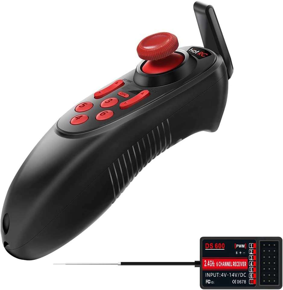
The Hotrc DS-600 is a very small remote control for mini droids or something like that.
It can be held in one hand and offers a reliable connection.
It is limited to 6 channels, but one remote control per hand offers a total of 12 channels.
There is even a rechargeable battery installed (although the runtime is only ~4h)
It even offers a Tankdrive mixing function.
The channels are all PWM channels (the exception is the 4+2 receiver).
Therefore no sum signal is possible.
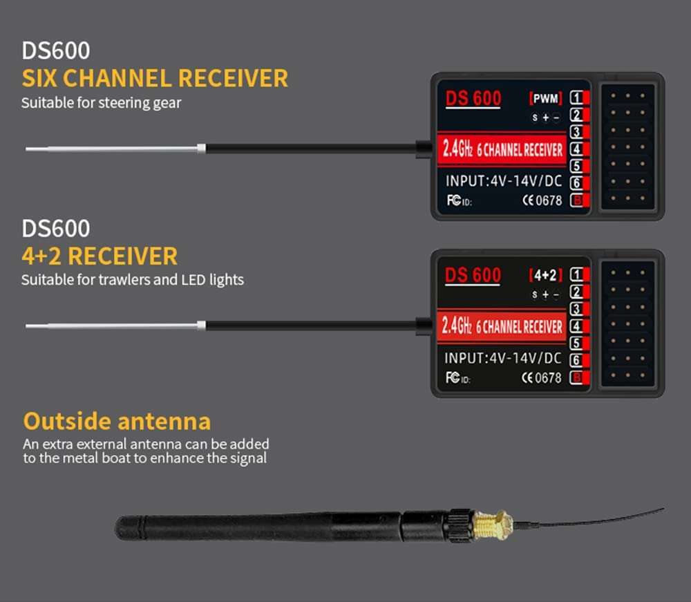
There are 2 recipients. The 6 channel PWM receiver and the 4+2 receiver.
The 4+2 receiver has only 4 PWM channels and 2 switching channels for LEDs on/off etc.
In this context, please make sure to read Greg Spata’s great modding tutorial:
https://bithead942.wordpress.com/2023/01/21/modifying-the-hotrc-ds-600/
Basic operation
Code matching steps
- Turn off the transmitter and receiver first;
- Plug the Coder into the “B” interface of the receiver;
- Connect the power cord to the corresponding channel interface of the receiver(The receiver light flashes quickly at this time);
- Turn on the transmitter power switch(The receiver light is always on at this time) ;
- Unplug the code pairing device, the code pairing succeeds Receiver LED status: flashing: it indicates that it is powered on, has no signal, and does not match.
- Steady on: indicates successful matching and pairing.
Charging instructions
The remote control has built-in: 1200MAH lithium battery, charging IC with protection function, battery built-in protection function, dual design; adapter please choose: 5V mobile phone charging head.
Charging instructions:
- The remote control needs to be turned off during the charging process,
- Red light charging status, green light fully charged status.
Mixing control function setting instructions
Function description The mixed control mode allows channel 1 and channel 2 to control two motors at the same time for throttle forward and backward or diffeential steering.
Setting method:
- The remote control is turned off first;
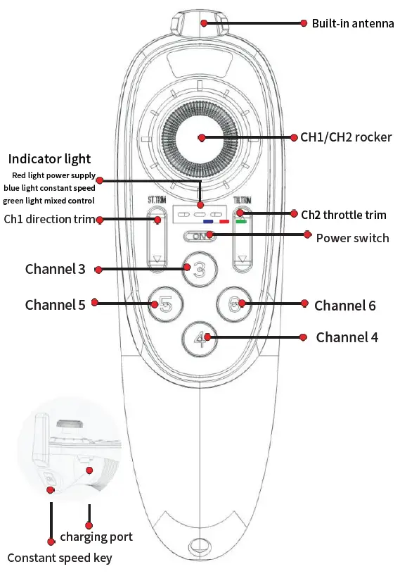
- Press and hold the 【channel 3】switch first, and then turn on the power switch of the remote control, the mixing indicator (green light) on the remote control panel will be on.
- The operation method of opening and closing the mixing control is the same, and the mixing control closing status indicator light will go out.
Out-of-control protection function setting instructions
Function Description The out-of-control protection function is a protection function for the receiver to lose signal, avoiding losses due to out-of control. It is mainly for setting the throttle channel. When the receiver does not receive a control signal, the receiver’s throttle channel will run to the originally set value to avoid misoperation. The default value of the out-of-control protection is the neutral point. Setting method
- Before setting the fail-safe protection, the transmitter and receiver need to be matched and coded successfully;
- Turn the transmitter and receiver on (the receiver signal light is on at this time);
- Control the throttle channel of the transmitter so that the throttle control server or governor enters the brake or stall state, and then keeps it motionless;
- At this time, insert the codec into the receiver “B” port (the receiver LED will flash at this time) And after 3 seconds, the light is always on, and the fail-safe setting is completed.
Function test
- Turn off the transmitter power,
- Check whether the servo of the throttle channel enters the position of the setting state.
Notice: The safe return position of the throttle servo is recommended to be set to the brake or neutral point. Do not set it to the throttle open position to avoid danger. The system defaults out of control protection functions as follows:
- Tram–the position of the steering servo is at the neutral point, and the throttle of the speed controller is at the neutral point.
- Oil truck–The position of the steering servo is at the neutral point, and the throttle servo is at the idle position.
1CH/2CH Positive and negative settings
Setting method
- The remote control is turned off first;
- Press and hold the [4 channels] switch without releasing it, then turn on the remote control power switch;At this time, you will hear a beep and the remote control enters the setting state.
- Note that you can only set the forward and reverse of one channel at a time Push the CH1 joystick or CH2 joystick to the maximum or minimum and you will hear a long beep to indicate that the setting is completed.
- Description of stroke amount setting
- Function Description The channel 1.2.3.4.5.6 stroke of the remote control can be adjusted; Note: Except for channel 2 when there is no action feedback during throttle adjustment channel 1.3.4.5.6. There will be action feedback during the adjustment process to facilitate observation of the adjustment status. Setting method
- The remote control is first turned off; Press and hold [OK fixed speed button] without releasing it, and then turn on the remote control power switch; (At this time, the 2 lights (red and blue) of the remote control will flash simultaneously).
- 【ST .TRIM】button plus and minus setting【Channel 1】Adjust the size of the direction stroke; (The factory default stroke amount has been appropriately reduced, and themaximum stroke amount to the minimum stroke amount is divided into 20 gears)
- 【TH .TRIM】Button addition and subtraction settings [Channel 2] Throttle stroke adjustment; (The factory default stroke amount is the maximum, the maximum stroke amount to the minimum stroke amount is divided into 5 gears)
- 【Channel 3.4.5.6】The maximum stroke amount to the minimum stroke amount is divided into 10 gears, cyclic adjustment; ( The factory default stroke amount is the maximum, the remote control mark channel button adjusts the corresponding channel stroke amount)
Note: The receiver’s antenna is mainly used to receive signals. Please do not pull or cut the antenna during use. The receiver’s antenna will receive stronger signals when it is in an upright state.
Receiver function setting instructions
Model Description This remote control has a variety of models of receivers to choose from and supports customization.
- 【CH6 Receiver】
- 【4+2 Receiver】
- There is an integrated receiver with brushed version power
Function Description
- 【CH6 Receiver】:The 6 Channels are all PWM signals.
- 【4+2 Receiver】:CH1 direction PWM signal, CH2 throttle PWM signal.(CH3 and CH5 can only use one channel at the same time, CH3 is the PWM servo signal, CH5 is the power signal, which is mainly used to control lights or trawl hooks, etc.; CH4 and CH6 can only choose one channel to use at the same time, and CH4 is the PWM servo Signal, CH6 is the power signal, which is mainly used to control lights or trawl hooks.)
- 【There is an integrated receiver with brushed version power】:This receiver integrates the receiver and the power controller. The receiver can be customized according to customer needs.
Specifications
| Model type | Model boat/net pulling boat/fishing boat |
| Channels | 6 |
| RF range | 2.4Ghz ISM(2.4006-2.483.5GHz) |
| RF power | 100mW |
| Modulation | GFSK |
| Spread spectrum | FHSS |
| Reaction speed | PWM 20ms |
| RF distance | Water surface: 300-500m, ground: 400-600m* |
| Receive sensitivity | -97dbm |
| Transmitter voltage | 5v |
| Receiver voltage | DC 4V – 14V |
| Gross weight | 70g |