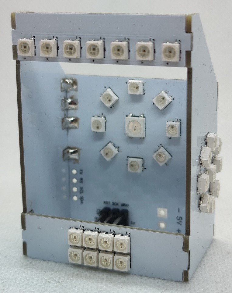
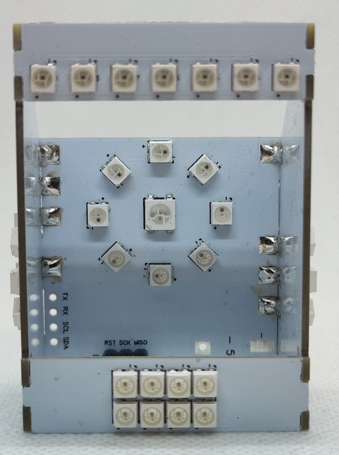
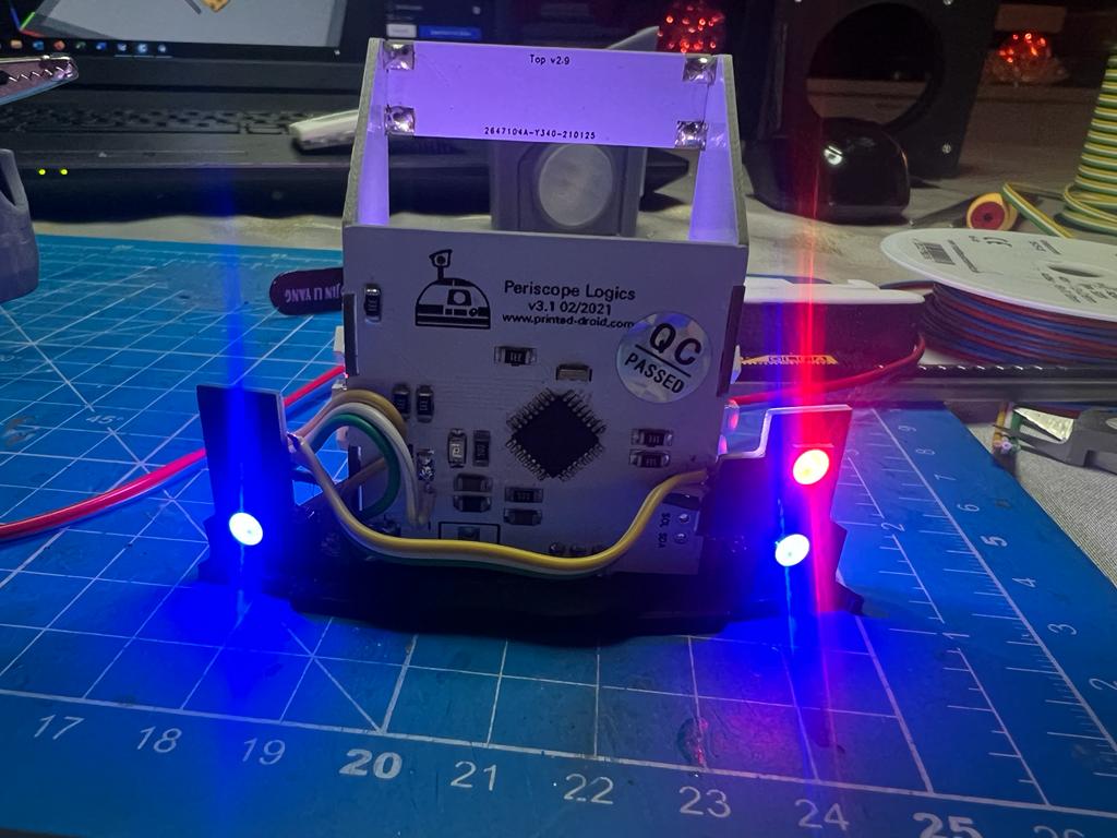
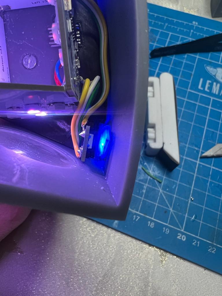
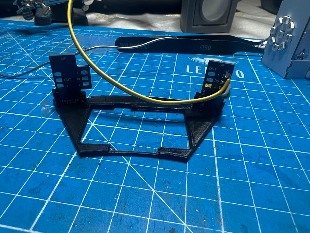
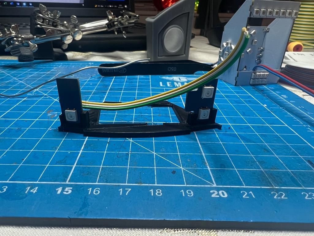
The Periscope Logics are a custom PCB kit for Matt Zwarts Domelift Periscope – but should fit almost all Periscopes.
It needs 5V and can run standalone or be controlled via serial command or I2C.
Firmware is still not final but running the needed sequences.
(we just want more sequences and full integration into the Benduino/Marcduino system)


ESP32 Version:
The ESP32 version is the latest version.
The advantages are that WiFi and bluetooth are available as additional connection options.
Mimir created a sketch to make the periscope board compatible with the Uppity Spinner:
https://github.com/rimim/R2D2_Periscope_esp32
To revert back to Serial change this line:
#define UPPITY_SPINNER_MODE
To this:
//#define UPPITY_SPINNER_MODE
Connect rotary board pin A to to RX, rotary board pin B to SDA, and rotary board pin C to SCL. Connect rotary GND pin to GND pin on the light kit
Programming the ESP32 Version:
You need an FTDI programmer.
Connect 5V and GND as usual.
Cross connect RX and TX (RX goes to TX and vice versa)
Start the upload in the Arduino IDE and wait till you see this in the output:
…..——…..—–…..—–
Then press and hold the flash button
Press the reset button briefly (reset is still pressed)
Release the reset button
The upload should now start.
EPS32 Pinout:
| Top Lights | IO33 |
| Bottom Lights | IO17 |
| Main Lights | IO27 |
| Left Lights | IO16 |
| Right Lights | IO25 |
| Rear Lights | IO26 |
| RX | IO3 |
| TX | IO1 |
| SDA | IO21 |
| SCL | IO22 |
Arduino 328P Version:
Same functions (except wifi & bluetooth) like the newer Esp32 version.
To revert back to Serial change this line:
#define UPPITY_SPINNER_MODE
To this:
//#define UPPITY_SPINNER_MODE
Connect rotary board pin A to to RX, rotary board pin B to SDA, and rotary board pin C to SCL. Connect rotary GND pin to GND pin on the light kit
Pinout corresponding to the sketch:
Pin 5 – Main Lights
Pin 10 – Right Side
Pin 3 – Left Side
Pin 2 – Bottom Leds
Pin 6 – Top Leds
Pin 9 – Rear Leds
Available at shop.printed-droid.com