The “old” Teeces V3 Dome Lighting System was developed by JoyMonkey and it is the most common used Light System for the Domelogics.
It’s an Arduino based system using Max7219CNG ICs to trigger 5 arrays of LEDs.
They run their own sketch but can be controlled with a Marcduino.
The successor of the Teeces is the R-Series Logic Engine which uses RGB Leds and a fibre optic cable for illumination.
The Printed Droid Teeces v4 version has some improvements:
- better tracing
- 3.5mm terminals
- reliable step down option
- smd components for the caps and resistors
- PSIs and RLD are labeled with the LED colors for easier placing and soldering the LEDs
- the Slim Teeces use an Arduino Nano for easier programming
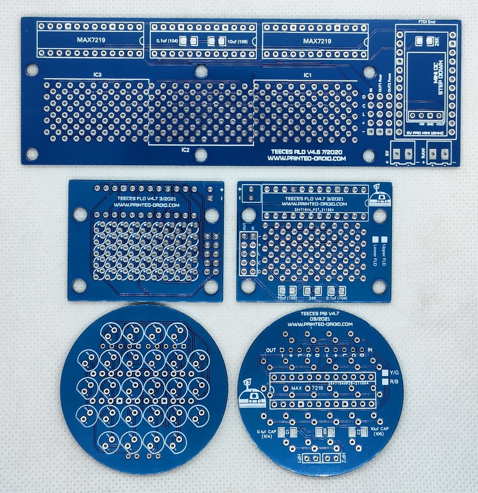
The Teeces kit consists of 5 PCBs.
The Rear Logic Display (RLD), 2 Front Logic Displays (FLD) and 2 Processor State Indicators (PSI).
They build a “chain” controlled by the Arduino sitting on the RLD who provides the LEDs with light pattern signals.
Regular Teeces:

Slim Teeces:

Regular vs. Slim:


You can buy a soldered Kit or make your own.
Available at shop.printed-droid.com
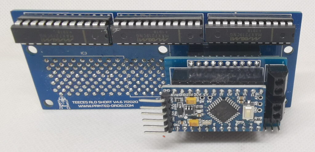
If you want to make your own use this the component list:
Boards and Wiring:
1. RLD-Board (Rear Logic Board)
- This board forms the foundation of the system.
- On the back of the RLD-Board is the Control Board, which manages the system’s operation. (Only Slim Teeces)
2. Control Board
The Control Board is directly connected to the RLD-Board and features six connections:
- RAW-Input: Input for up to 12V (not recommended but possible).
- 5V-Input: Recommended input as it provides stable power supply for the system.
- RX/TX (Serial Communication): Terminal for serial data transmission (receive and send).
- Three 5 PIN connections:
- OUT-2-Front: For the front components.
- OUT-1-Rear: For the rear components (where the PSI-Board is connected).
- Input: Not currently used.
3. Wiring of the 2 Front Logic Boards (FLD) and the Front PSI Board
- The OUT-2-Front connection of the Control Board is connected to the Input of the first Front Logic Board (FLD).
- From the OUT of the first FLD, the connection continues to the Input of the second FLD.
- From the OUT of the second FLD, the connection goes to the Input of the Front PSI Board.
- All connections use a 5-pin cable, wired pin-to-pin:
- The pins Plus, Minus, L, C, and D must be connected 1-to-1 to ensure correct communication between the components.
4. Wiring of the Rear PSI Board
- The OUT-1-Rear connection of the Control Board is connected to the Rear PSI Board (Process Status Indicator).
- The connection is made using a 5-pin cable, wired pin-to-pin:
- The pins Plus, Minus, L, C, and D must be connected 1-to-1 to ensure correct data transmission.
- This connection runs directly from the Control Board to the input of the Rear PSI Board.
5. Regular Teeces System
- In addition to the Teeces Slim System, there is the regular Teeces System.
- Unlike the Slim version, the regular Teeces System does not have a separate Control Board.
- All connections are located directly on the RLD-Board.
Further Information and soldering tutorial from Joymonkey:
Original instructions for the Teeces:
http://joymonkey.com/run/files/V3.2%20Kit%20Sheet%20Sept%202012.pdf
More information:
Joymonkey:
http://joymonkey.com/run/index.php?pg=tools
Astromech Wiki:
http://astromech.net/droidwiki/Teeces_V3_Dome_Lighting_System
Tutorial for Teeces logioc programming:
https://astromech.net/forums/showthread.php?8980-Quick-tutorial-for-Teeces-logic-programming