FlthyHPs – Flthy Holo Projectors

Estimated reading time: 7 min

Overview

The FlthyHP is a sytem to light up your Holoprojectors and add servo movement. It was developed by Ryan Sondgeroth (aka FlthyMcNsty).
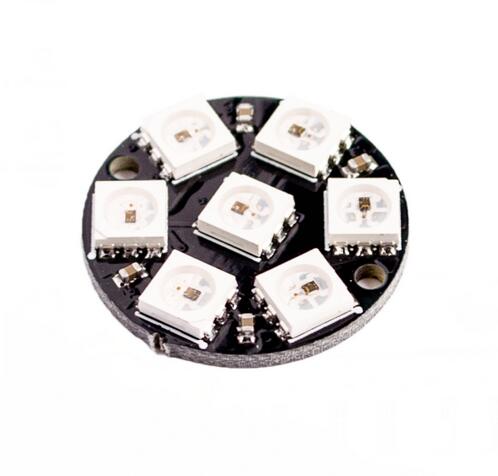
It’s based on the Flthy Breakout Board, 7″bit” RGB Led rings and a 16 Channel 12bit PWM Servo Driver Board (only needed if you want servo movement).

If you’re using Benduinos/Marcduinos, you don’t need the servoboard. The Holoservos are connected with the slave Benduino/Marcduino.

The complete setup needs an Arduino Pro Mini (or similar), 3 RGB Led and optional 3 slip rings (3 or 6 wires, whatever is cheaper). There’s also a Arduino Breakoutboard that makes connecting easier.

I’d reccomend to use a Slip Ring for the Holoprojectors to reduce the risk of ripping wires through motion or strangers hands.

If you want the holos to move you’ll need an additional PWM Servoboard or a Marcduinosystem.

Flthy Arduinoboard with Arduino Pro Mini
7-Bit-WS2812-5050-RGB-LED
PWM Board
“Holo” with LED & Slipring

This is how my LED is mounted and you can see the Slip Ring at the back

Instructions for software v2.0 and up

Summary of Changes in Version 2.0

This version of the FlthyHPs software is a complete architectural refactor of the original v1.9/1.8 sketch. It was rebuilt from the ground up to improve stability, performance, and maintainability by implementing modern, professional coding practices. Below is a detailed explanation of the key changes.

1. Replaced String Class with char Arrays

  • What was changed? The Arduino String class, which uses dynamic memory, was entirely removed. All command processing now uses a fixed-size C-style character array (char[]), managed by a CommandBuffer class.
  • Why was it changed? This is the most critical stability improvement. The String class can cause heap fragmentation on microcontrollers, leading to unpredictable crashes over time. Using a fixed-size character buffer prevents these memory issues entirely, ensuring the system runs reliably for long periods.

2. Implemented a Robust Command Parser & Error Handling

  • What was changed? Command processing is no longer a single, large block of code. It has been broken down into modular functions: parseCommand, validateCommand, and processCommand. The system now explicitly checks if a command is valid before attempting to execute it.
  • Why was it changed? This makes the system far more robust. It can now gracefully handle malformed or invalid commands without crashing. The modular design also makes the code cleaner and easier to debug and extend in the future.

3. Added Readable Error Messages

  • What was changed? If an invalid command is sent, the system now responds with a human-readable error message in the Serial Monitor (e.g., Error: Invalid Device) instead of just a numeric code.
  • Why was it changed? This makes testing and troubleshooting significantly easier and more intuitive. The user can immediately understand what went wrong.

4. Implemented a Timer Class for Timing Management

  • What was changed? A SimpleTimer class was created to manage all millis()-based timing logic (e.g., for auto-twitch intervals and animations).
  • Why was it changed? This encapsulates complex timing logic into clean, reusable objects. It eliminates multiple parallel global variables and makes the main loop() much easier to read and understand.

5. Re-Implemented Timed Command Parsing

  • What was changed? The command parser can now correctly handle the pipe syntax (|) for timed sequences (e.g., A006|15 to run for 15 seconds).
  • Why was it changed? This restores a key feature from the original sketch, allowing for the creation of automated sequences that run for a specific duration without requiring a separate “stop” command.

6. Optimized Memory Usage (PROGMEM & Data Structures)

  • What was changed? The large, constant BASIC_COLORS array was moved from SRAM into the microcontroller’s Flash memory using PROGMEM. Additionally, data types were optimized (e.g., using uint8_t and enum class) to use the minimum necessary memory.
  • Why was it changed? SRAM is a very limited resource on an Arduino. Moving large, unchanging data to Flash frees up hundreds of bytes of critical SRAM, leading to a more stable program with more memory available for runtime operations.

7. Replaced Floating-Point Math with Integer Math

  • What was changed? Calculations that previously used decimal numbers (double or float) have been rewritten to use only whole numbers (integers).
  • Why was it changed? Integer arithmetic is dramatically faster on 8-bit microcontrollers like the Arduino Nano. This change provides a significant performance boost, making the sketch more responsive.

8. Consolidated All “Magic Numbers” into Constants

  • What was changed? All hard-coded numbers (like pin numbers, animation limits, or command codes) have been replaced with descriptive, named constants (e.g., Config::WAG_CYCLES or LedFunction::RAINBOW).
  • Why was it changed? This makes the code self-documenting and easy to maintain. A value can be changed in one central place (Config namespace), and the change will apply everywhere it’s used.

9. Improved Readability and Organization

  • Namespaces & Enums: All configuration constants are now grouped in a Config namespace, and all states/commands are defined using type-safe enum class. This prevents naming conflicts and makes the code’s intent clear.
  • Reduced Code Duplication: Repetitive logic was extracted into reusable helper functions (e.g., setAutoMode), following the “Don’t Repeat Yourself” (DRY) principle. This makes the code shorter and less prone to errors.
  • Added a help command: For user convenience, a help command was added to display a summary of available commands directly in the Serial Monitor.

Software Guide: Flthy Holoprojectors v2.0 for Benduino/Dome AIO

Based on the original concept by: Ryan Sondgeroth (FlthyMcNsty)

1. Introduction: The Role of this Sketch

This project provides a software solution for creating advanced, multi-pixel LED effects for your droid’s three holoprojectors (HPs). It uses 7-pixel Adafruit NeoPixel Jewels to produce vibrant, life-like animations like hologram flicker, short circuits, and rainbow patterns.

In a Benduino (BetterDuino) Dome AIO system, this sketch runs on a dedicated Arduino Nano, which acts as an I2C “slave” to your main Benduino controller. The Benduino is the “master” and handles all dome logic and servo movements. It sends commands to this HP controller via I2C to trigger specific LED animations.

2. Software Setup & Configuration

This is your to-do list for preparing the sketch before uploading it to your Arduino Nano.

STEP 1: Install Required Libraries

Use the Library Manager in the Arduino IDE (Sketch > Include Library > Manage Libraries...) to install the following:

  1. Adafruit NeoPixel
  2. Adafruit PWM Servo Driver Library
  3. Servos.h (also known as SlowServoPCA9685 by Big Happy Dude).

Note: Even though your setup does not use the servo functions of this sketch, the code requires these libraries to be present to compile correctly.

STEP 2: Configure the v2.0 Sketch

Open the v2.0 sketch file. All user-configurable settings are at the top.

  • #define DEBUG: Uncomment this line (// #define DEBUG -> #define DEBUG) to enable detailed diagnostic messages in the Serial Monitor. This is very helpful for testing.
  • #define NEO_JEWEL_RGBW: Uncomment this only if you are using the RGBW (4-color) version of the NeoPixel Jewels instead of the standard RGB (3-color) version.
  • Auto Twitch Settings: You can adjust the enableTwitchLED array to control if the LEDs should play random effects automatically. The timing and duration of these events can be tweaked in the LED_TWITCH_INTERVAL and LED_TWITCH_RUN_INTERVAL arrays.
  • Default Colors: You can change the default colors for the “Leia” (DEFAULT_COLOR) and “Short Circuit” (SHORT_COLOR) effects.

Settings to IGNORE for Dome AIO:

The following settings relate to servo control, which is handled by your Benduino. You do not need to change them.

  • #define ENABLEBASICHP
  • #define ENABLERC
  • The HP_POS and HP_POS_BASIC arrays. No servo calibration is needed for this sketch in your setup.

3. Flashing the Sketch to your Arduino Nano

  1. Open & Configure: Open the v2.0 sketch file in the Arduino IDE and perform the configuration steps from Section 2 above.
  2. Connect Arduino: Connect your Arduino Nano to your computer via USB.
  3. Select Board & Port: In the Arduino IDE, go to Tools > Board and select "Arduino Nano". Then go to Tools > Port and select the correct serial port.
  4. Upload: Click the “Upload” button (the right-arrow icon).

4. Command Reference

You can test all commands using the Arduino IDE’s Serial Monitor (Baud: 9600, Line Ending: “Newline” or “Both NL & CR”).

IMPORTANT FOR DOME AIO USERS:

In your setup, this controller exclusively manages the LEDs. Your Benduino handles all HP movement. Therefore, only Type 0 (LED) commands and Sequence (S) commands will produce effects. Type 1 (Servo) commands sent to this board will be ignored.

Command Structure: D[T##][Options][|duration]

  • D (Device): The target holoprojector(s).
    • F, R, T: Front, Rear, Top
    • A: All HPs
    • X, Y, Z: Combinations (Front+Rear, Front+Top, Rear+Top)
    • S: Major sequence affecting the whole system.
  • T (Type): 0 for an LED function.
  • ## (Function): The two-digit code for the action (see lists below).
  • Options (Optional):
    • C[0-9]: Set Color (e.g., C1 for Red, C5 for Blue, C0 for Random).
    • S[0-9]: Set Speed for the Dim Pulse function.
  • Duration (Optional): | followed by seconds (e.g., |15 for 15 seconds).

LED Functions (Type 0)

  • 01: Leia Sequence (blue hologram effect).
  • 02: Color Projector (flickering hologram in a specific color).
  • 03: Dim Pulse (color slowly pulses on and off).
  • 04: Cycle (a single pixel rotates around the jewel).
  • 05: Solid Color.
  • 06: Rainbow Sequence.
  • 07: Short Circuit (erratic flashing).
  • 96-99: Various modes to clear the LEDs and enable/disable auto-twitch.

Major Sequences (Device S)

These commands control the auto-pilot modes of the LEDs.

  • S1: Leia Mode (Plays Leia sequence on Front HP, others off).
  • S4: All Off (Disables auto LED functions and turns off LEDs).
  • S5: Reset to Auto (Enables auto LED twitch with default sequences).
  • S6: Reset to Auto (Enables auto LED twitch with random sequences).
  • S7-S9: Similar to S4-S6 but enables the “Off Color” feature.

Command Examples:

  • F005C1: Turn the Front HP LEDs to Solid color, using Color 1 (Red).
  • A006: Run the Rainbow sequence on All HP LEDs.
  • T003S8|30: Run a slow (S8) Dim Pulse on the Top HP for 30 seconds.
  • S4: Stop all automatic LED functions.

5. Integration with Benduino (BetterDuino Firmware)

Your Benduino board acts as the master controller and will send I2C commands to this HP LED controller.

  • I2C Address: The default I2C address for this sketch is 0x19 (decimal 25). Ensure this does not conflict with any other devices on your I2C bus. You can change it in the Config namespace if needed.
  • Command Format: The BetterDuino firmware uses a specific wrapper to send I2C commands. The format is &[address],"[command]\r".
    • &: Specifies an I2C command.
    • 25: The I2C address of the HP LED controller.
    • ,": Delimiter and start of the string command.
    • [command]: The FlthyHPs command you want to send (e.g., A006|15).
    • \r: A required “carriage return” character to terminate the command.

Example Benduino Command:

To make all holoprojectors display the rainbow effect for 15 seconds, you would send this command from your Benduino configuration (e.g., R2-Touch app):

&25,"A006|15\r"

Instructions for software v1.9 and below

It’s pretty simple to get this working. You just solder straight header pins to the PCB, a small screw terminal and an IC socket for the Arduino (you can use female oin headers instead). You have to flash the Arduino with the Sketch, vonnect some wires and that’s it. You need to provide the LEDs (and Servos) with a constant 5v Source like the Arduino.
If you want to use servo movement, just ad the PWM Driver board and add 6 SG90 Servos.

For a detailed instruction please read Flthys instructions here:
http://2geekswebdesign.com/FlthyHPs/Manual/FlthyHPsManual_v1.8.pdf

After everything is hooked up and programmed you can expect something like this:

I inserted a plane convex lens and a small plastic diffusor, which looks great for the produced light

Random Servo movement from the Flthy Board

Servomovement, Colors, Speed etc is all configured via the Arduino Sketch.
Please check out the original instructions and sources below:

Flthys Website:
http://www.2geekswebdesign.com/FlthyHPs/
Manuals:
http://www.2geekswebdesign.com/FlthyHPs/Manual/
Current Manual:
http://www.2geekswebdesign.com/FlthyHPs/Manual/FlthyHPsManual_v1.8.pdf
Arduino Sketches:
http://www.2geekswebdesign.com/FlthyHPs/Sketches/

Building a Flthy Holosystem on the cheap

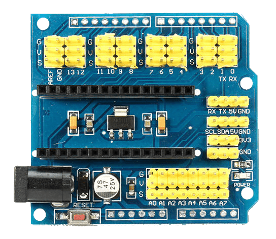
You also can also use a cheap Nano Expansion Board from Aliexpress, eBay etc. instead of the FLTHY Board

What is needed?
1x Arduino Nano Expansion Board (~1.50USD from eBay or 0.50USD from AliExpress)

Expansion Board V3.0 For NANO

3x 7 Bit RGB Led WS2812 5050 Led rings (~1USD each from Aliexpress)

7 Bit RGB Led WS2812 5050 Led

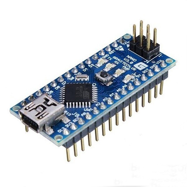
1x Arduino Nano (~1.50USD from Aliexpress / eBay)

Arduino Nano

That’s basicall it. The Nano + the extension board has the same Pins as the normal FlthyHoloboard. All you have to do is find the correct pins on the extension board.
The normal Flthy Holosketch should work perfect.

Pin2 (digital) Front Holo Led
Pin3 (digital) Rear Holo Led
Pin4 (digital) Top Holo Led

Additional Pins are:
Pin9 (digital) RC IN

If you’re using the Marcduinos for the Servos, that’s it. If you use the pwm servoboard you need to connect them at the extension board here:

Nano Extension Board / Original Flthy BoardPWM Servo Board
Ground / GGND
Pin9 (digital) / OEOE
SCL / CSCL
SDA / DSDA
5V / VccVCC
5V / VV+
Tags:
Was this article helpful?
Dislike 0 11 of 11 found this article helpful.
Views: 6928
Previous: Arduino Pro Mini Breakoutboard
Next: Astrocomms