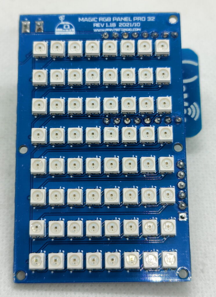
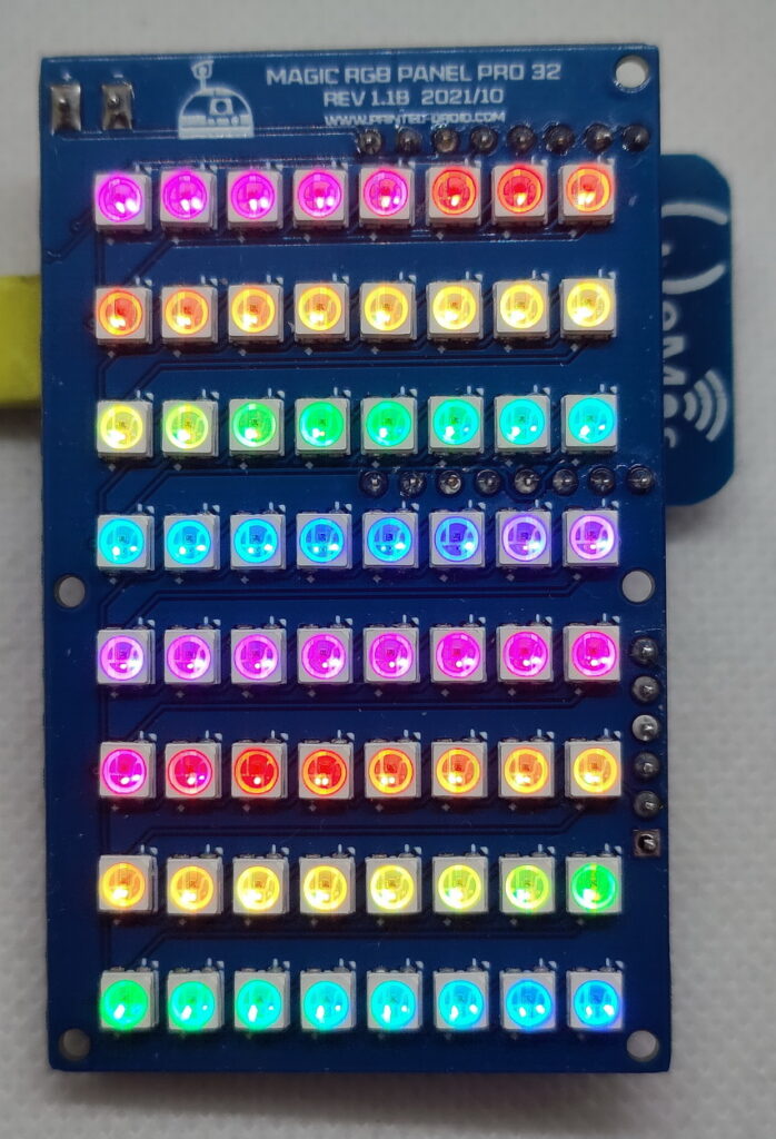
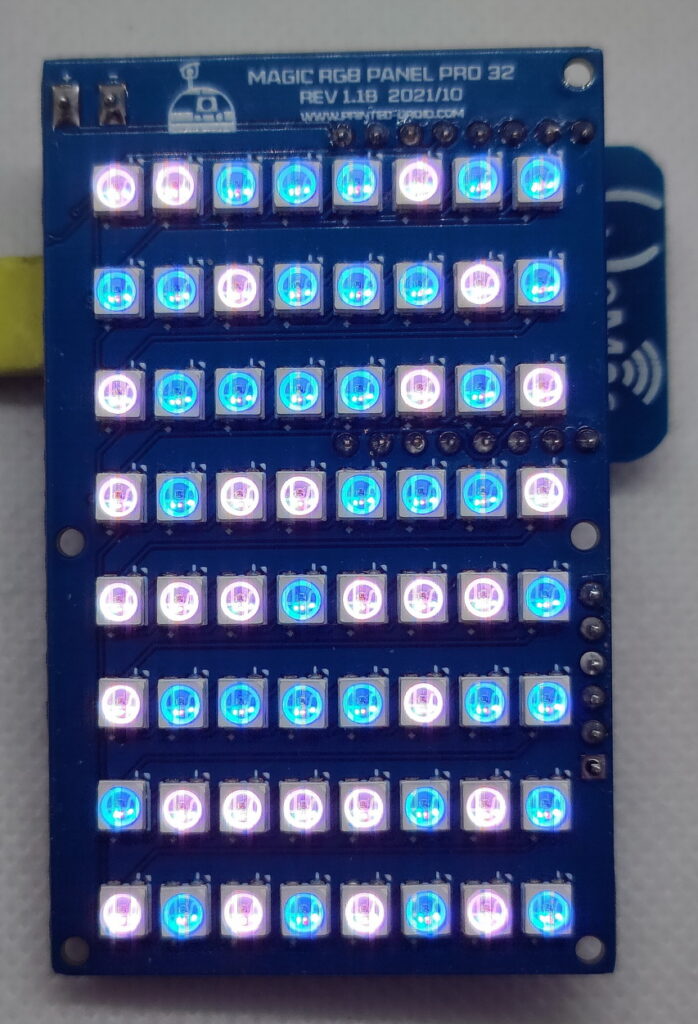
The Magic Panel 32 board has a full-color 8×8 Led matrix on the front.
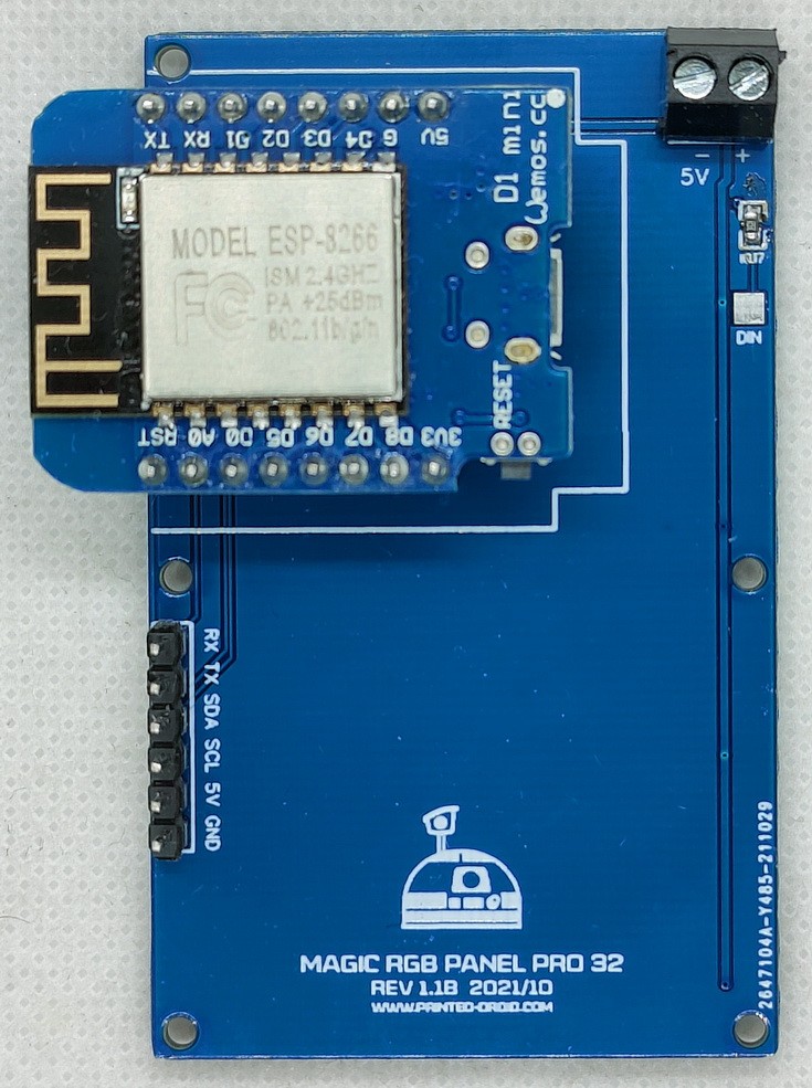
The system is controlled via an ESP8266 or ESP32 on the back.
It’s purpose is to fit into the upcoming full wireless (except power wires -of course) control system
The system can be operated standalone (power on / off) or offers a command structure that can be controlled via a serial, I2C or wireless.
The ESP on the back can also be left out, as the digital input pin is also externally accessible.
Pinout ESP8266:
Pin 0 – Leds
Pin 3 RX – RX
Pin 1 TX – TX
Pin 4 – SDA
Pin 5 – SCL
Pinout ESP32
Pin 17 – Leds
Pin 1 RX – RX
Pin 3 TX – TX
Pin 21 – SDA
Pin 22 – SCL
Available at shop.printed-droid.com
Connection:
Benduino AIO: Slave 2 pins
Marcduino: Slave Board – Slave/MP pins
I highly reccomend to connect it via serial and not via i2c
Adapted sketch for the Printed-Droid.com Magic Panel using Fastled
The Full description of all command sequences are listed below. These are called using either i2c or serial and supplying the mode number as listed.
The Code has two modes of operating. It is possible to set this during runtime of the panel, however the default is controlled in the code below. To set the Defaul mode, change the variable “alwaysOn” to be either true or false. The default here is false.
If alwaysOn is set to False, the patterns will display for a given time, and then turn off.
If alwaysOn is set to True, the pattern will display until the T00 (off) command is received. (or loop until T00 is received).
To change the Default, Command P0 will set to “false”, Command P1 will set to “true”, overriding the default for this session.
The Magic Panel uses JawaLite commands to trigger the patterns. Currently only A, D, P, and T commands from the JawaLite spec are supported.
Command A will turn the panel on
Command D will turn the panel off
Command P will set the default panel mode as described above.
Command T will trigger a numbered pattern. Txx where xx is the pattern number below.
When sending i2c command the Panel Address is defined below to be 20. The command type and value are needed. To trigger a pattern, send character ‘T’ and the value corresponding to the pattern list below to trigger the corresponding sequence.
Sequences must be terminated with a carriage return (\r)
On the MarcDuino i2c can be connected from either the Master or Slave
e.g. &20,x54,2\r – This will turn on the MP for ~2 seconds.
When sending commands via serial, no address is required as Serial is a point to point communication protocol.
Sequences must be terminated with a carriage return (\r)
To use the MarcDuino Serial triggering, connect Pin 3 of the Magic Panel (Rx) to the “To Slave” Signal pin on the
MarcDuino Slave.
e.g. %T2 – This will turn on the MP for ~2 seconds.
Mode 0 – Turn Panel off
Mode 1 – Turn Panel on Indefinately
Mode 2 – Turn Panel on for 2s
Mode 3 – Turn Panel on for 5s
Mode 4 – Turn Panel on for 10s
Mode 5 – Begins Toggle Sequence: Top and Bottom Half of Panel Alternate
Mode 6 – Begins Alert Sequence (4s): Panel Rapidly Flashes On & Off
Mode 7 – Begins Alert Sequence (10s): Panel Rapidly Flashes On & Off
Mode 8 – Begins Trace Up Sequence (Type 1): Each Row of the MP lights up from bottom to top filling entire panel
Mode 9 – Begins Trace Up Sequence (Type 2): Each row of the MP lights up from bottom to top individually
Mode 10 – Begins Trace Down Sequence (Type 1): Each row of the MP lights up from top to bottom filling entire panel
Mode 11 – Begins Trace Down Sequence (Type 2): Each row of the MP lights up from top to bottom individually
Mode 12 – Begins Trace Right Sequence (Type 1): Each column of the MP lights up from left to right filling entire panel
Mode 13 – Begins Trace Right Sequence (Type 2): Each column of the MP lights up from left to right individually
Mode 14 – Begins Trace Left Sequence (Type 1): Each column of the MP lights up from right to left filling entire panel
Mode 15 – Begins Trace Left Sequence (Type 2): Each column of the MP lights up from right to left individually
Mode 16 – Begins Expand Sequence (Type 1): Panel expands from center filling entire panel
Mode 17 – Begins Expand Sequence (Type 2): Ring of pixels expands from center of panel
Mode 18 – Begins Compress Sequence (Type 1): Panel compresses from outer edge filling entire panel
Mode 19 – Begins Compress Sequence (Type 2): Ring of pixels compresses from outer edge of panel
Mode 20 – Begins Cross Sequence: Panel is lit to display an X for 3s
Mode 21 – Begins Cyclon Column Sequence: Each column illuminated one at a time from left to right back to left. (like the Cylons from Battlestar Galactica)
Mode 22 – Begins Cyclon Row Sequence: Each row illuminated one at a time from top to bottom back to top. (like the Cylons from Battlestar Galactica)
Mode 23 – Begins Eye Scan Sequence: Each row is illuminated from top to bottom followed by each column left to right. (like the eye ball scanners in the Mission Impossible movies)
Mode 24 – Begins Fade Out/In Sequence: MP gradually and randomly fades out and then fades back in the same manner.
Mode 25 – Begins Fade Out Sequence: MP gradually and randomly fades out (Similar to the Short Circuit Sequence on Teeces).
Mode 26 – Begins Flash Sequence: MP flashes rapidly for 5 seconds (Similar to Alarm Sequence)
Mode 27 – Begins Flash V Sequence: Left and Right Half of Panel Alternate
Mode 28 – Begins Flash Q Sequence: Alternating quadrants of MP flash rapidly
Mode 29 – Begins Two Loop Sequence: Dual pixels are lit opposite each other completing a loop around the 2nd ring from panel edge.
Mode 30 – Begins One Loop Sequence: A single pixel is lit individually completing a loop around the 2nd ring from panel edge.
Mode 31 – Begins Test Sequence (Type 1): Each pixel of the MP is lit sequentially from row 0, column 7 to row 7, column 0 until panel is filled, then unlit in the same order.
Mode 32 – Begins Test Sequence (Type 2): Each pixel of the MP is lit indivually from row 0, column 7 to row 7, column 0.
Mode 33 – Begins AI Logo Sequence: Displays the AI Aurebesh characters for 3s (…that we see all over our awesome packages from Rotopod and McWhlr)
Mode 34 – Begins 2GWD Logo Sequence: Displays the Characters 2-G-W-D sequentially every 1s (…shameless, I know.)
Mode 35 – Begins Quadrant Sequence (Type 1): Each Panel Quadrant lights up individually (TL, TR, BR, BL)
Mode 36 – Begins Quadrant Sequence (Type 2): Each Panel Quadrant lights up individually (TR, TL, BL, BR)
Mode 37 – Begins Quadrant Sequence (Type 3): Each Panel Quadrant lights up individually (TR, BR, BL, TL)
Mode 38 – Begins Quadrant Sequence (Type 4): Each Panel Quadrant lights up individually (TL, BL, BR, TR)
Mode 39 – Begins Random Pixel Sequence: Random pixels flashe individually for 6s
Mode 40 – Begins countdown from 9 to 0 (takes 10 seconds)
Mode 41 – Begins countdown from 3 to 0 (takes 4 seconds)
Mode 42 – Begins Alert Sequence (4s): Panel Randomly Flashes On & Off, mimics the original MarcDuino code
Mode 43 – Begins Alert Sequence (8s): Panel Randomly Flashes On & Off, mimics the original MarcDuino code
Mode 44 – Begins Smiley Face
Mode 45 – Begins Sad Face
Mode 46 – Begins Heart
Mode 47 – Begins Flash Checkerboard sequence. Flashes small squares in a checkerboard pattern
Mode 48 – Begins Compress In Type 1 – Fills the rows from TL/BR in half row increments 5 times
Mode 49 – Begins Compress In Type 2 – Fills the rows from TL/BR in half row increments then clears in the same order 5 times
Mode 50 – Begins Explode Out Type 1 – Fills the rows from Centre Out in half row increments 5 times
Mode 51 – Begins Explode Out Type 2 – Fills the rows from Centre Out in half row increments then clears in the same order 5 times
Mode 52 – Begins VU Meter – Randomly ramp up/down on the columns to simulate a VU Meter. (Type 1)
Mode 53 – Begins VU Meter – Randomly ramp up/down on the rows to simulate a VU Meter. (Type 2)
Mode 54 – Begins VU Meter – Randomly ramp up/down on the columns from the top to simulate a VU Meter. (Type 3)
Mode 55 – Begins VU Meter – Randomly ramp up/down on the rows from the right to simulate a VU Meter. (Type 4)